This class works really well in parallel with Physical Computing. While we delve more into the basics of electronics in P Comp, we jumped right into implementing simple interactions with the Flora in the second part of the Costumes class. We used pre-existing code that Kaho provided to light up a LED on the Flora with the press of a button.
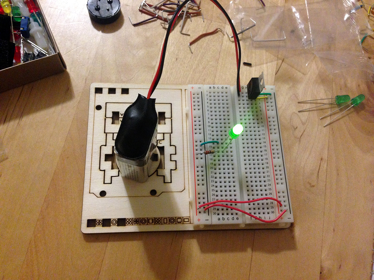
Lighting up LED with one switch.

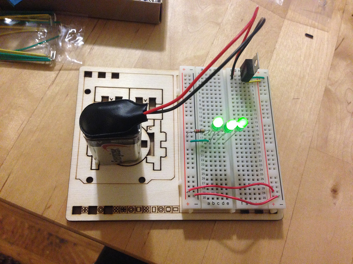
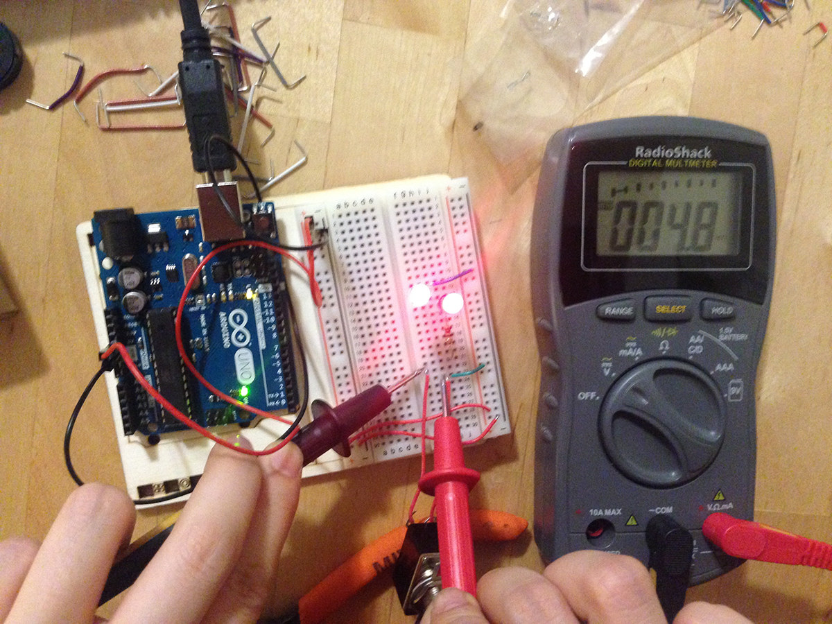
Lighting up LED with two buttons.
It was fairly easy to make adjustments to the code and configurations of the connections to try various ways of lighting up the LED and even to input text with a button.
Printing strings by pressing on a switch.
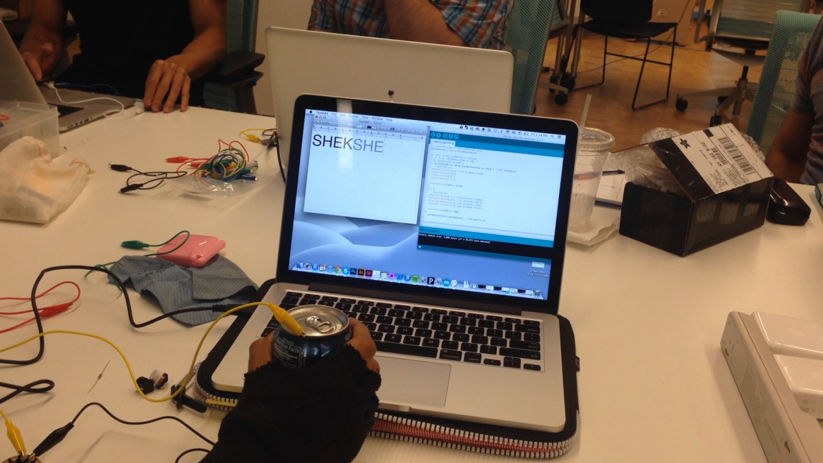
Printing strings with DIY switch.
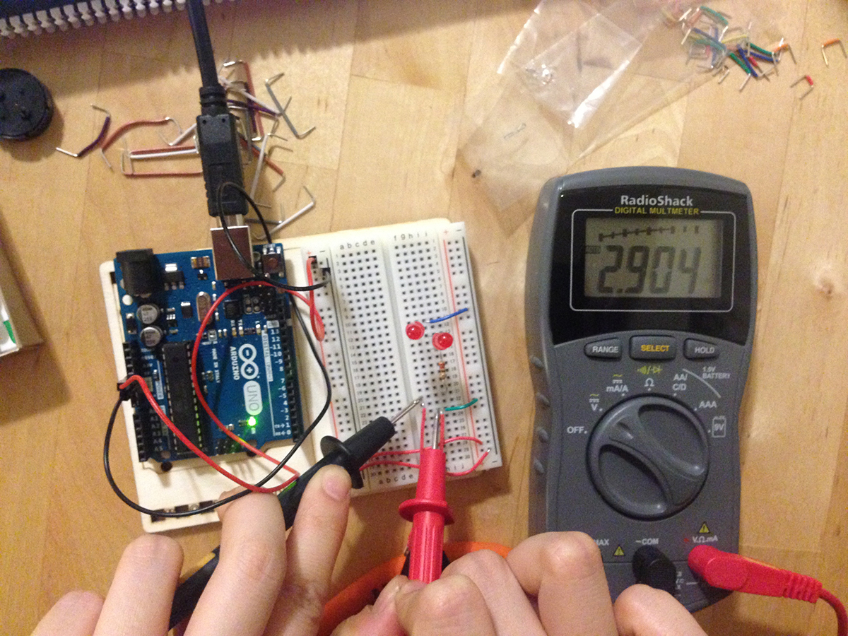
We also tried using conductive fabric and material as a switch. One of the takeaway from this was that, because contact from fabric is not as secure as a conventional switch, we need to “debounce” in the code to make the response more stable. Debouncing checks the lastButtonState and ensure that it’s different from the current buttonState. Again, we used pre-existing code to do this. I’ll need to look more into this to have a better understanding. There was a lot of tickering around with the code and connections until things worked. I’m making baby steps to building my own mind altering costume.