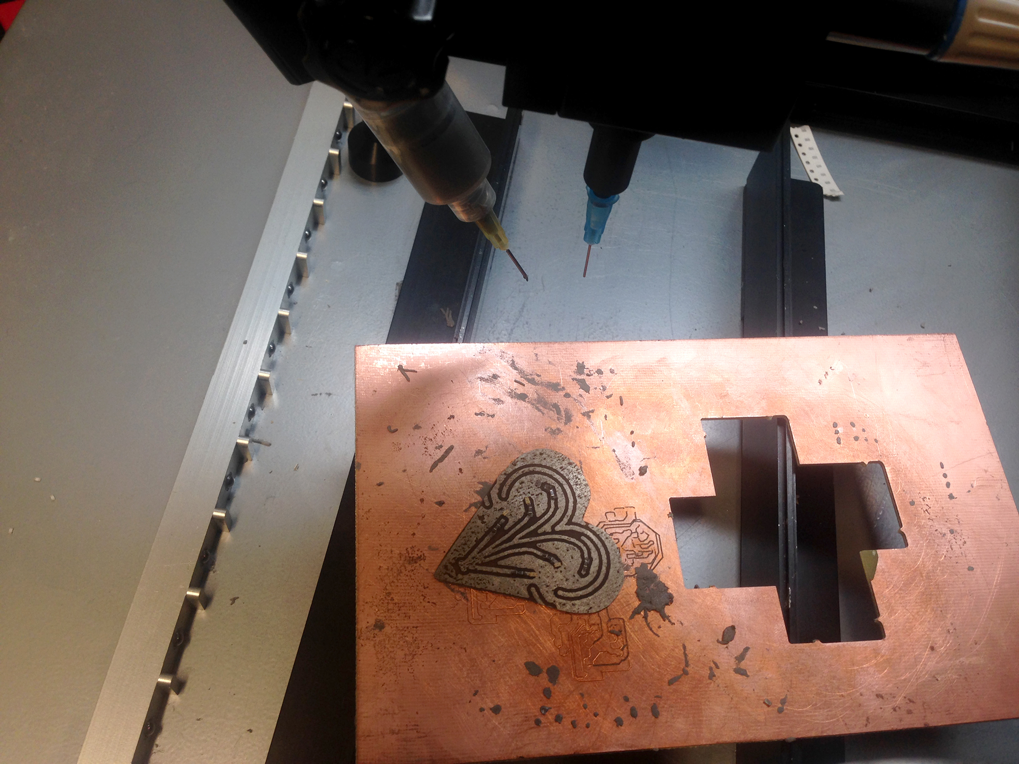
Class was replaced by a Roland milling workshop this week. We used a machine in the PCB lab that was modified by the incredible Andy Sigler, who conducted my workshop. Andy had created a web interface that allowed us to work with our EAGLE file and control the machine. The setup is very junk-shelf-fabulous and caters to ITPers’ needs specifically. We can print hundreds of our own boards right on the floor! Think of all the madness we can create.
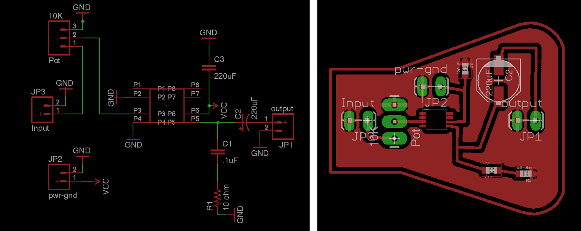
Here are the steps to PCB milling with our Roland Modela. We used Sam’s bike notification device schematic.
1. Measure the precise thickness of the board
2. Open Nodela (our custom milling web interface) and drag the file on to the program
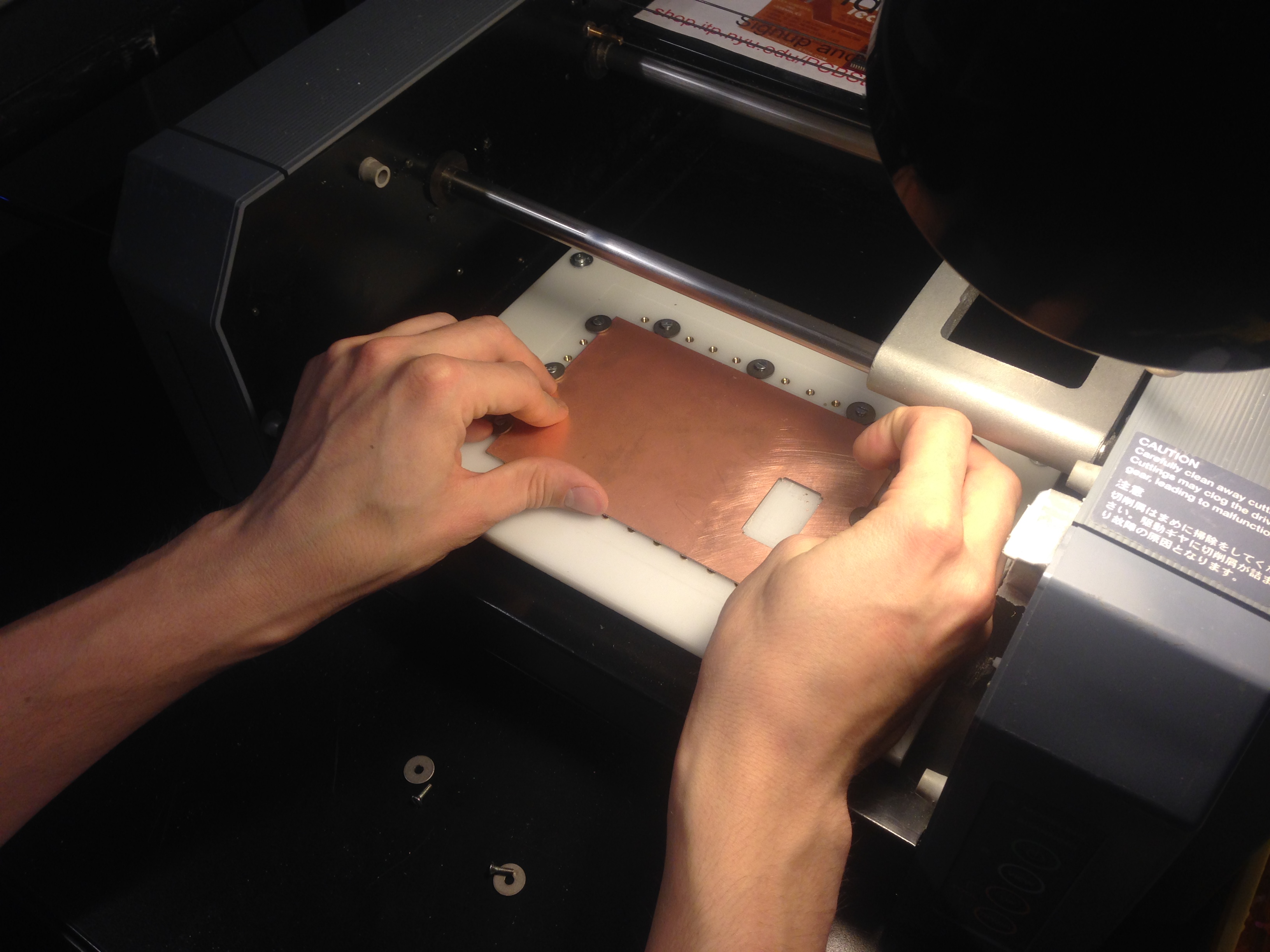
3. Tighten the screws around the board

4. Make sure there are no leftover job on the machine by pressing up and down simultaneously. If the light blinks, press delete job
5. Screw in the 1/32 bit and set Z origin
6. Run the machine. Once the 1/32 bit is done, replace with the 1/64 bit and run the machine again
7. Screw in the drill bit and drill any holes in the design
8. Replace the drill bit with a flat drill bit and run the machine to trace the shape of the board
9. Vacuum the board

10. Almost there! Take the board out, scrape it and clean it up.
There’s also tutorial on setting up the EAGLE file for the milling machine here.
From etching PCB board with vinegar and acid to milling it with custom crafted machine and web interface, I’ve begin to see making circuit boards as a craft and even an art form. I’m excited for the possibilities that can come out of my new found ability to design and print my own circuits. There are a couple of projects that I’d love to build with custom boards. One is a collection of wearable Bluetooth devices that would create small mesh networks. I’ll have to figure out what is feasible for the next few weeks.