Paper Fortune Teller and GSM: putting it together

Getting started with Arduino and GSM module. Abe manning the computer.

Getting started with Arduino and GSM module. Abe manning the computer.

IMG_1212

Wiring up all 8 sides of the paper fortune teller.

I wanted to try using conductive paint, so we chose to use capsense for each of the eight sensors. By gently tapping on the conductive paint, the sensor value reading goes up on the Arduino, providing us a threshold to trigger a text message send event on the GSM module. We had to use the analog pins since we need two pins for each sensor. Without connect the GSM, the capsensor worked pretty well.

By touching each of the sides, the value reading went up dramatically.

IMG_1449

Tangle of wires: connecting the GSM module to the paper fortune teller setup.

It took a bit of trial and error to get the GSM to work with the rest of the setup. We had to switch some of the pins for the sensors to make room for the GSM RX and TX pins.

It sends text messages!

IMG_1459

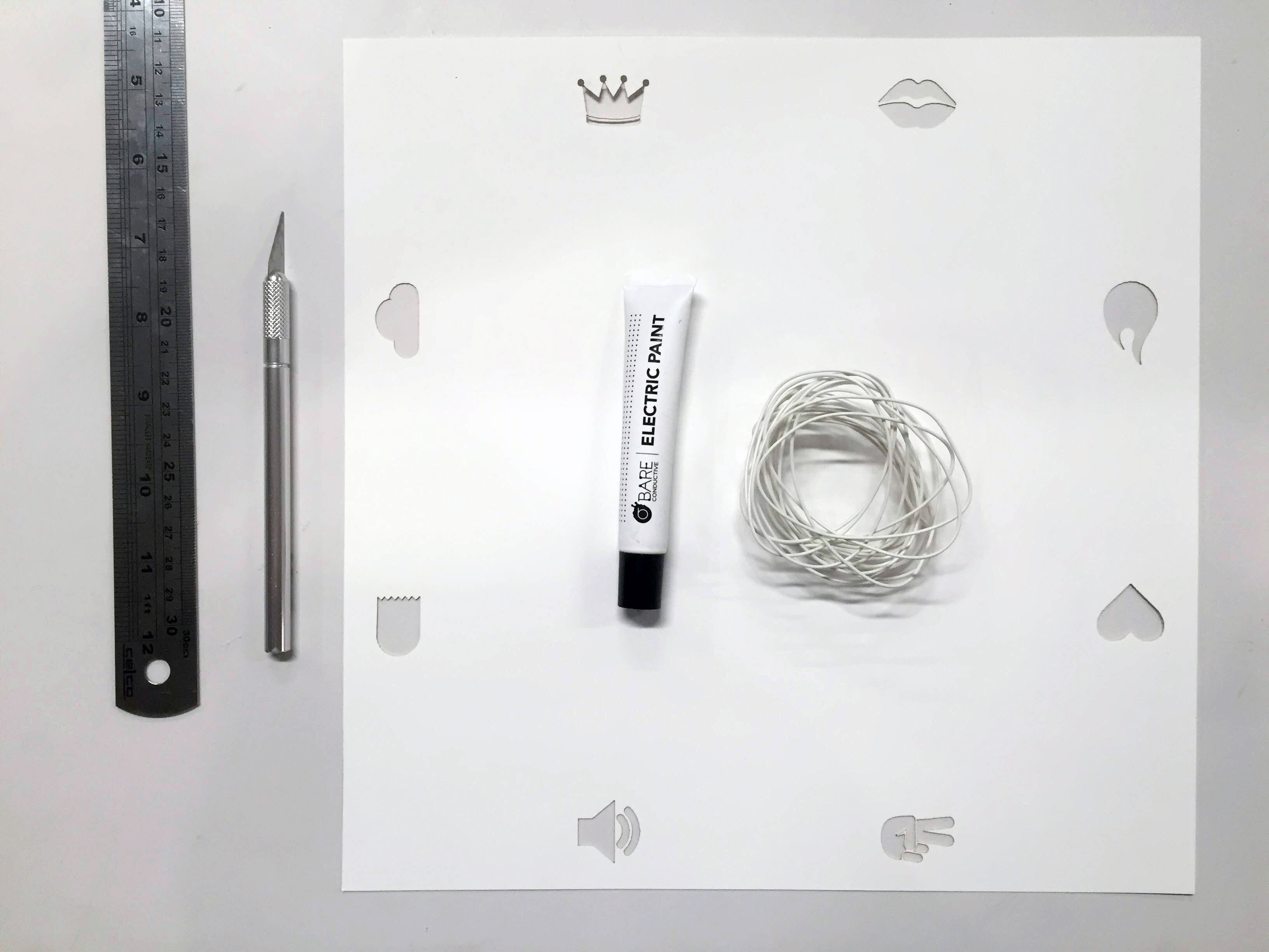
Materials for the paper fortune teller.

The conductive paint works better for capsense when there’s large enough areas to touch. So instead of using numbers, we are going with icons, which has larger areas to be filled with conductive paint.

IMG_1463

Paper Fortune Teller rough prototype 1.

To hide the wiring, I designed the paper fortune teller to fold over the conductive paint and wires by cutting holes on the inside of the paper. All wires for the eight sensors would come out from the bottom center.


Paper Fortune Teller

large-cootie-catcher

For Towers of Power’s final project, I’m working with Jason Dunne and Abe Rubenstein to create a GSM driven paper fortune teller. Like with the paper fortune teller game that we played as kids, the player picks a side and counts the number of pinches and pulls. Unlike that game, the player sends a text message to a designated recipient by tapping the picked side .

Before partnering with Jason and Abe, I had wanted to make a dice phone. Depending on which side the dice lands a corresponding text message would be sent out. We all liked the idea of random communication that the player would have little control over. I also liked the idea of a screen-less interface for a phone. We thought about other random games/toys, such as the magic 8 ball and Russian roulette, and decided on a paper fortune teller.

This was our original bill of materials:

Velostat/Linqstat (one square meter to be cut into 12 pieces): $15.
Arduino GSM Shield/Quectel M10/Antenna: $90.
Origami Paper: $10.
Contact Tape: $10.
Misc: $10.

Hello LED

IMG_4801

The first time I tried using the GSM module to send a text, I made the dumb mistake of not turning on the module. So it worked this time. I used the code that Benedetta had emailed us.

Sending SMS from GSM module.

Sending SMS from GSM module.

A modest next step: turn on a LED with a text. For now, I’m able to receive texts by sending them through the GSM module with CoolTerm, but I can’t receive any messages on the GSM module. I’ll need to figure out how to receive a message, match it, then change the LED pin output to HIGH.

UPDATE:

I attempted again with the white GSM module. I can read SMS with CoolTerm now, but there seems to be a long delay. It takes a few seconds for the messages to show. If I use the command AT+CMGL=”ALL”, only the first part of the first message would display correctly. The rest of the messages are in gibberish. I tried changing the delay that follows Serial.write(inChar); in the code. But this didn’t help.

Reading SMS in CoolTerm.

Reading SMS in CoolTerm.

I also tried to turn the LED on by texting I, and turning it off by texting O. After about 10 secs of texting I, the LED would turn on. But typing O did not work. Also if I change the letter in the code from I to O, the LED would not turn on. Another issue I had was that after testing with my SIM card for a while, I wouldn’t be able to read anymore SMS on that card though I was still able to send SMS out. I had to switch to another SIM card to continue testing and reading SMS.

This is how it worked when I text “I” to turn on the LED:

Here’s the code:

Question

Is Serial.write(mySerial.(read)) writing +CMTI: “SM”,sms# each time? Perhaps this is why typing I would turn the LED on – because +CMTI contains the letter I. If this is the case, what is an effective way to check for +CMTI: “SM”,sms#, mySerial.print() the AT commands for reading SMS, skip through the metadata for the SMS, and read the actual SMS message?