Last week I didn’t do the breadboard and multimeter labs because of poor time management. Though we went through most of them in class and I was able to make my LEDs light up with the help of Benedetta and Sweta (thanks!), I figured that I should try them again on my own so that I get the fundamentals and reduce the chance that I’ll set anything on fire in the future.
Below are some of the results:
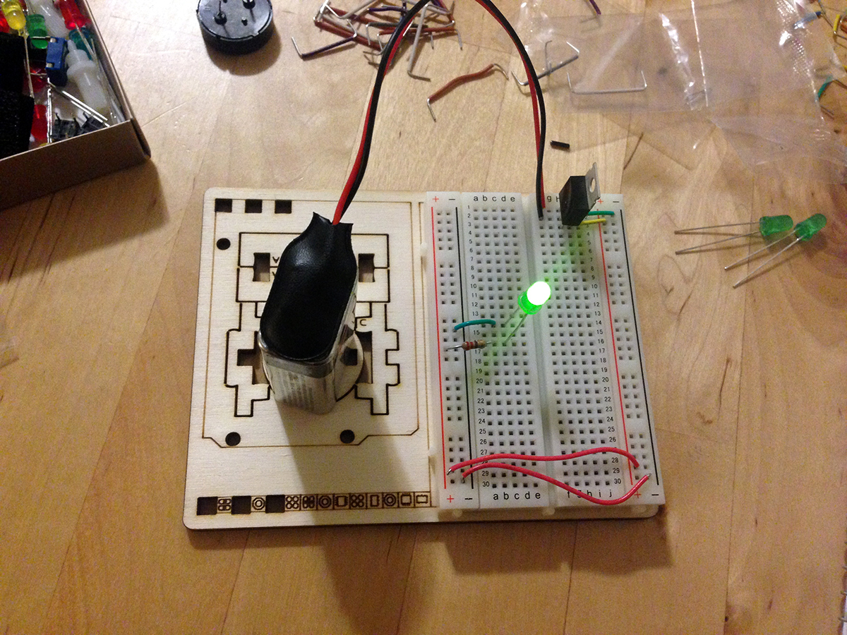 1 LED with voltage regulator + 9V battery: Yay! It’s alive.

2 LEDs connected in series

3 LEDs in connected in series: Boo. I forgot that the voltage regulator converts voltage from 9V (batter) to 5V. Each LED uses about 2V, so 3 of them would need more than 5V. I wonder what would happen if I remove the voltage regulator, and let the 9V go directly to the series of 3 LEDs?
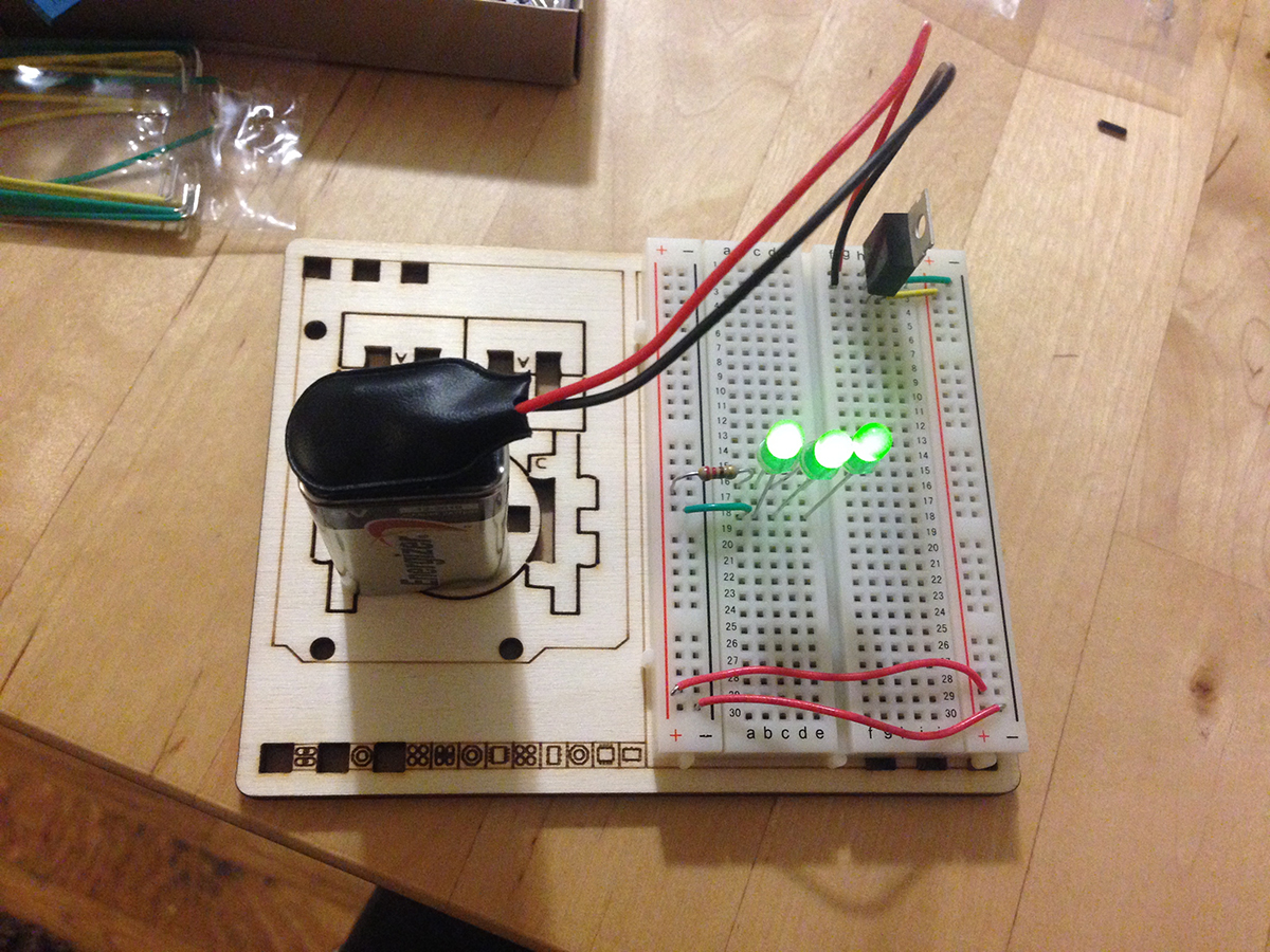
3 LEDs hanging out in parallel: This time it works, because the voltage is not split up between each of the LED. Each LED uses the same amount of voltage in this case.
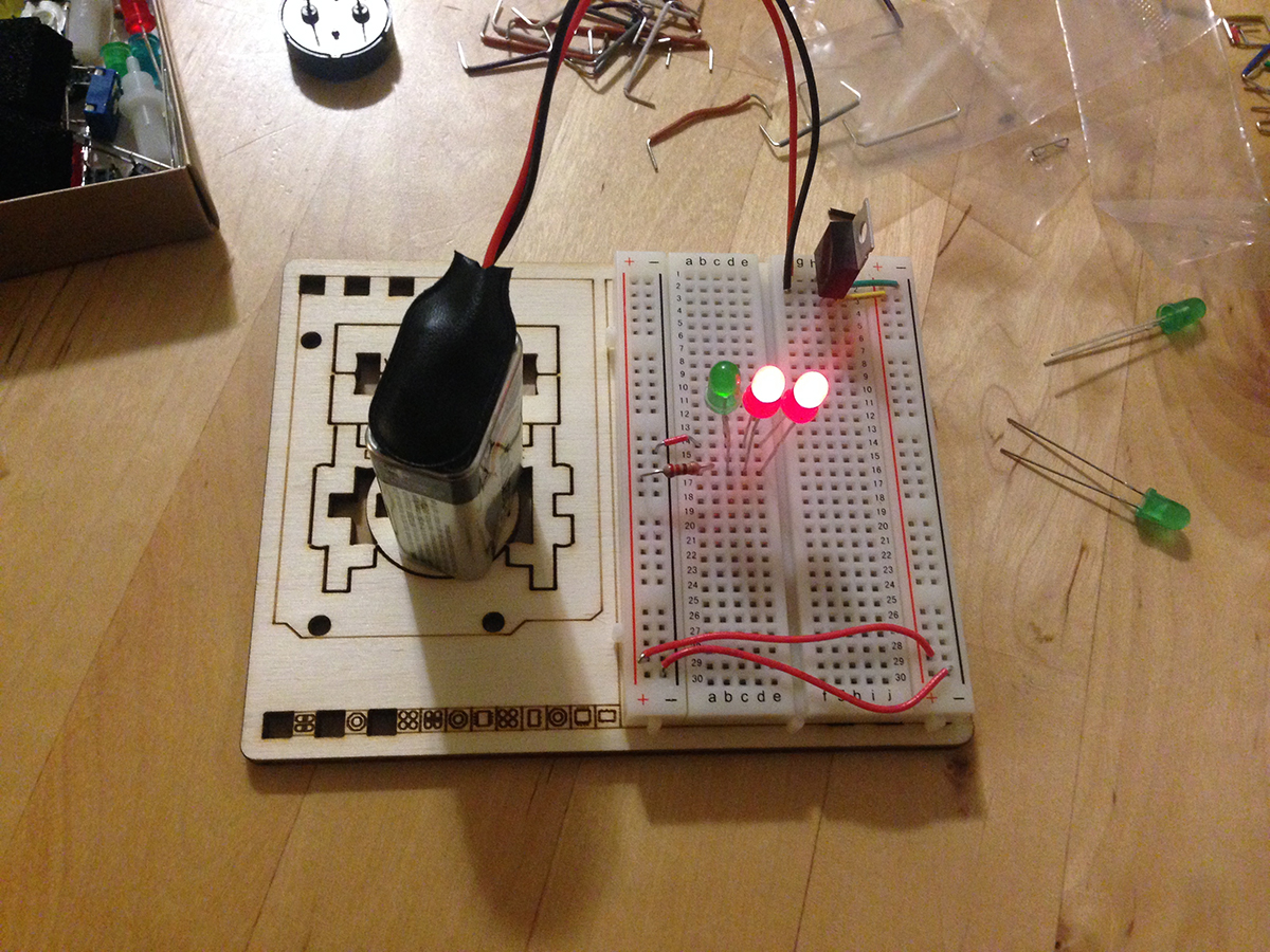
3 LEDs in parallel: This time the red LEDs are much brighter than the green one. The red LEDs uses less voltage than the green one, so is this prompting the current to pass through the red ones and not the green one? Would this potentially damage the green LED?

1 LED with Arduino built in 5V

1 LED with switch OFF: This is strange. Why is the switch measured at 3.8V when it’s turned off???
 1 LED with switch ON: And now the switch is at 0V. Why? Is it because the switch acts like a piece of continuous wire when it’s turned on?
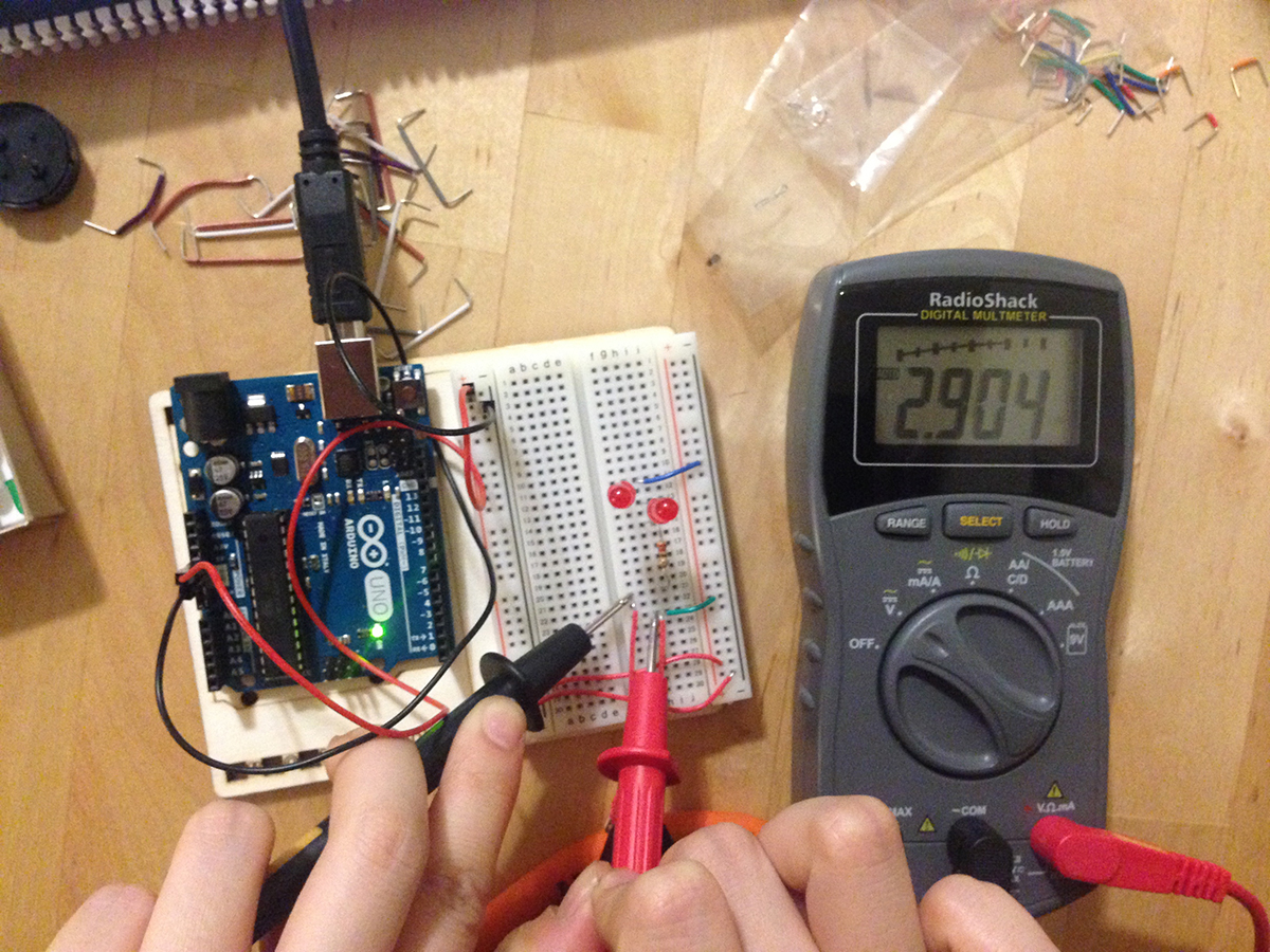
2 LEDs in series with switch OFF: I tried this again with 2 LEDs and measuring at the end of the wires. Again, the switch measured at around 3V when turned off.
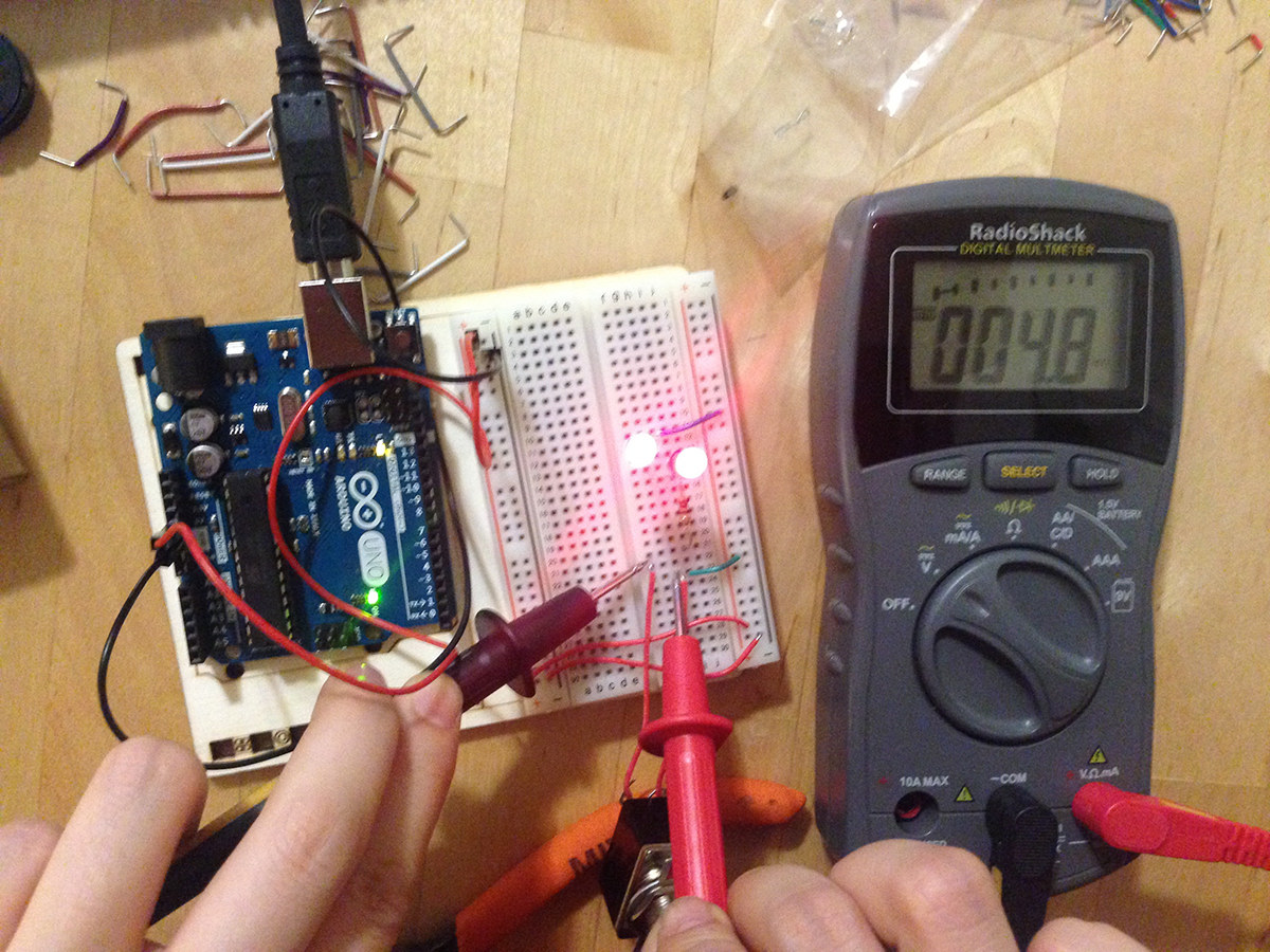 2 LEDs in series with switch ON: Again the switch measure at very little V, 4.8mV which is 0.0048V, when it’s switched on.