When reading multiple sensors a question that comes up is “which value corresponds with which sensor?” There are two ways to set sensor values in order: punctuation method, which involves punctuating each set of data uniquely, and call-and-response (handshake) method, which works very much like it sounds, sending one set of values at a time by setting the programs to call and respond to each other.
We tried each method in this lab, neither worked very well for me. And I have a lot of questions regarding the additional code.
This is what I’ve learned so far:
Punctuation method
To send data from the Arduino, we use Serial.print() and Serial.println() to send out each set of values, separated by commas Serial.print(“,”);.
To receive the values in Processing, we add myPort.bufferUntil(‘\n’); in setup() so that the string of values would be saved to the buffer and read together. In the serialEvent() function, the string is read with myPort.readStringUntil(‘\n’);. Then trim out any whitespace character (newline, carriage returns, spaces, tabs) with trim(stringx), split the values at each comma with split(stringx, ‘,’);, convert the values into integers and store them in an array, for instance int sensor[] = int(split(stringx, ‘,’));.
There are a few downsides to this method, namely the program may slow down if the buffer is full and that we can’t easily send binary values.
Call-and-response method
In the Arduino IDE, we setup a new function establishContact(). This function sends out a message until receives data from Processing. We check for data by checking whether Serial.available() is greater than 0 (true) or less then/equal to 0 (false). We call for this new function in setup(). Then, with an if statement, make sure that the strings of values in loop() would only send when Serial.available() is greater than 0.
In Processing, we check for contact with a new variable boolean firstContact = false;. In serialEvent() we let the program first check if the message from the Arduino is the right one with myString.equals(), then send back a character with myPort.write() to start receiving actual data. If firstContact is true, the code from the rest of serialEvent() would run, trimming, splitting, converting, and storing the values.
Issues:
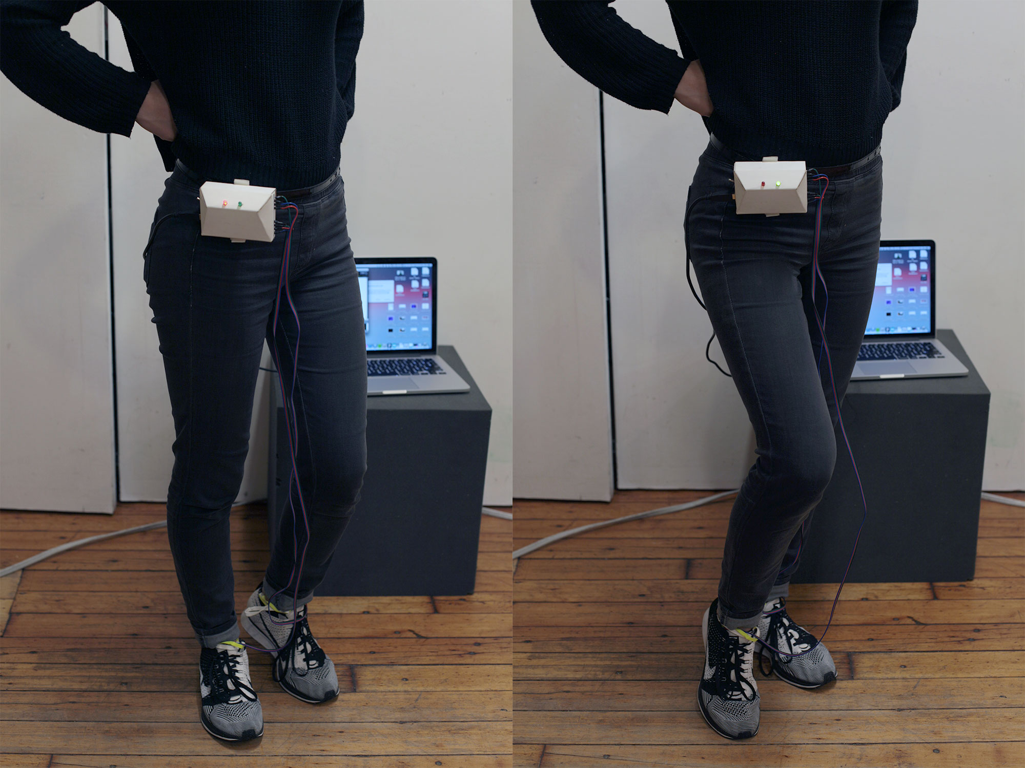
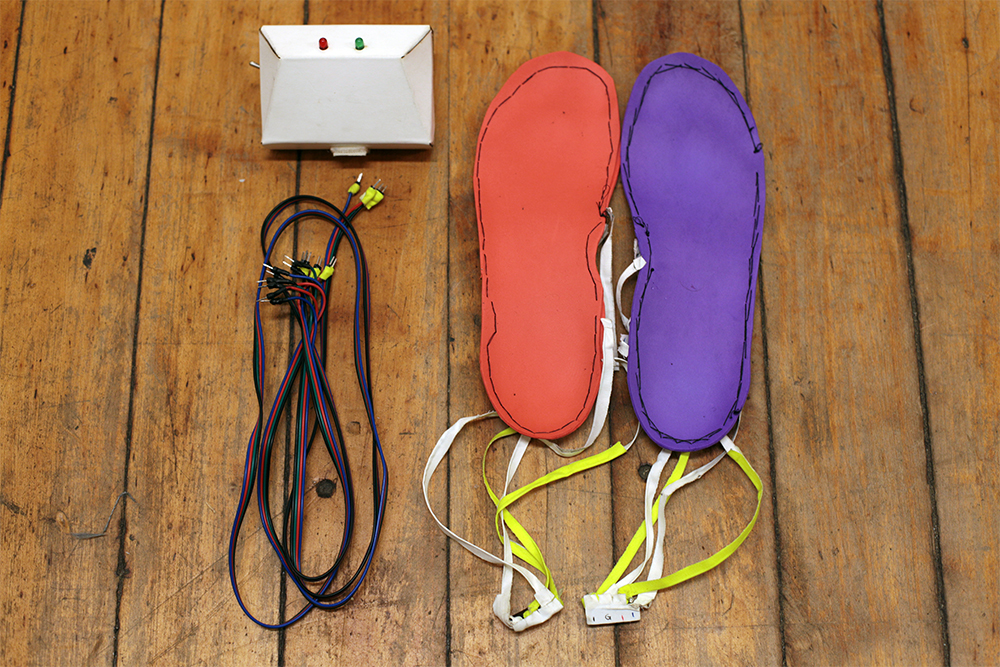
- With the lab (make a simple DIY mouse), my digital input worked well, allowing the ball to appear and disappear from the screen. But with the ball fluttered about when I moved the accelerometer. Instead of moving on the x and y axis smoothly, the ball was all over the place.
- Often the program didn’t even run. It displayed an error message.
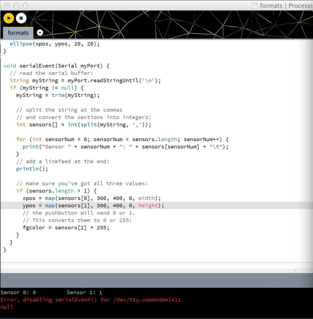
Error message in Processing.
Questions:
- Why is the call-and-response method better for sending binary data, even though it’s also sending and receiving strings with commas, then trimming, splitting, and storing them in a buffer? Also, wouldn’t this also slow down the program if the buffer gets full?
- Why do we need to call-and-respond between the programs?
- Explain more about the new functions in Arduino IDE and Processing. e.g. Serial.available(), trim(), split(), myPort.bufferUntil(), myPort.readStringUntil(), myString.equals(), etc.
Values show up properly in the Arduino IDE serial monitor.
Digital input works. Issues with analog input values.