For my second lab assignment, I connected a digital input and output circuit and an analog input circuit. (images below) The difference between a digital input and an analog input is that digital input can only sense two states (that’s why it’s also called binary input), on and off, and analog input can read a variable voltage. The range of an analog input is usually between 0 and the maximum voltage that the micro-controller can take. But the range can change depending on the physical context. In these instances, I should use the real range rather than the maximum range of the analog sensor.
There are various differences in working with digital input versus analog input. For one, an analog input requires an analog-to-digital converter (ADC) to read the voltage change and convert it into digital form, because the micro-controller can only read two input values, 0V and 5V. The ADC is built in the Arduino. With a digital input there is not need to convert the voltage.
Secondly, an analog input is less stable than a digital input. To smooth out the dips and spikes that goes into the circuit when inputing with an analog sensor, I need to decouple the input with a decoupling capacitor. (Capacitors are used to smooth out signals, by storing energy when the current is passing through and releasing it later.) Also, I should introduce a small delay after reading each sensor, to give the micro-controller time to stabilize before reading the next sensor.
Digital output is pretty straightforward – it turns something, such as a LED, on or off.
Issues:
I had some issues with digital I/O when I tried to make my own switch with metal sheets. The LEDs lit and responded to the switch, but didn’t follow the correct order of the program, i.e. yellow off, red on when switch is off and the reverse then the switch is on.
Questions:
I’m still not sure how to find the real range of an analog sensor in practice.I had encountered debouncing in another class when we used the Flora. What’s the difference between decoupling and debouncing?How do you know which size of decoupling capacitor to use in an analog input circuit?
Other:
I briefly looked at the serial monitor for input data, but I still don’t totally understand how it works. I’ll look more into that.

Digital I/O

Digital I/O with one button.
Digital I/O with DIY button. **Issue: both LEDs are lit when the switch is off, when the yellow LED should be off.

Digital I/O with DIY switch2. **Issue: again, both LEDs are lit when the switch is off.

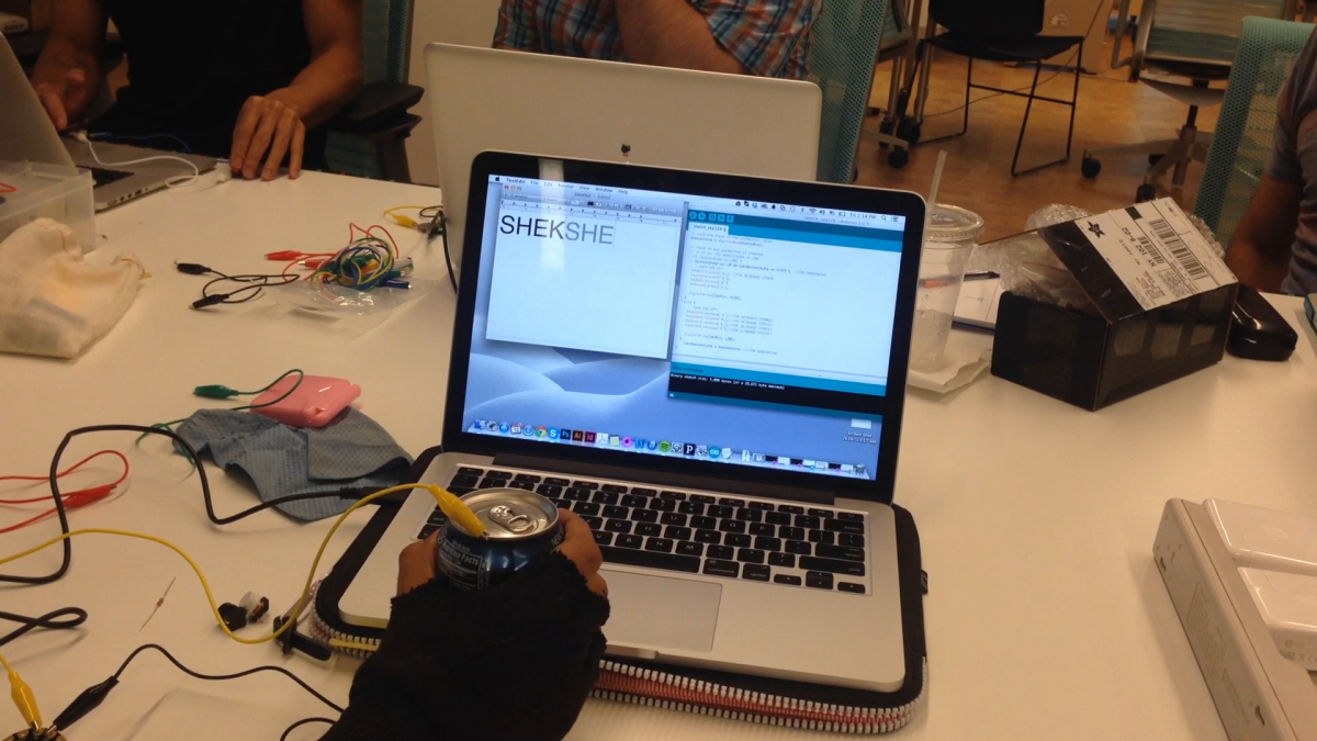
Analog input.
Analog input with a potentiometer.

Analog input with a force sensing resistor.