
How to build a flex sensor.
More info on Velostat.

Materials.

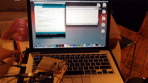
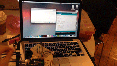
Completed flex sensor.
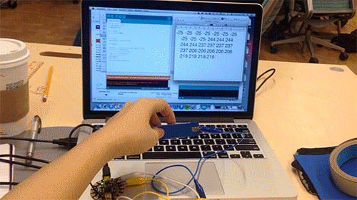
Reading flex sensor.
How to build a flex sensor.
More info on Velostat.
Materials.
Completed flex sensor.
Reading flex sensor.
This week’s lab was about analog output. An example of an analog output is the change of brightness in a lamp. A digital output would merely turn the lamp on or off in this instance. A micro-controller such as an Arduino is digital and can only take digital inputs and produce digital outputs. Last week we learned that micro-controllers use an analog-to-digital converter (ADC) to take analog inputs.
For analog output, the micro-controller creates pseudo-analog voltage with pulse width modulation (PWM). This means that the micro-controller basically fakes an analog voltage by producing a series of digital voltage pulses at regular intervals that are so fast (at micro or even nano seconds) it would be perceived as a varying voltage by the output device and humans. What is really varying is the effective voltage produced by these pulses. The effective voltage changes depending on the ratio between the pulse width – the period of high pulse – and the period of low pulse.

Pulse width modulation.
For the lab, we changed the state of a servo motor and the tone produced by a Piezo capsule through analog output from the Arduino. The servo motor output was done through PWM, turning the motor 180 degrees each time. The tone change was through change in frequency. This is different from PWM in that the series of digital voltage pulses are not produced in regular intervals; instead the total width from low pulse to high pulse back to low changes, resulting in differing frequencies which in turn is perceived as changing tones to our ears.

Left: PWM. Right: Frequency.

Servo motor analog output.
Analog output: servo motor from Jiashan Wu on Vimeo.

Controlling the tone with photo sensors.
Analog output: tones from Jiashan Wu on Vimeo.

Using the note constants to make a simple keyboard.
Analog output: tones2 from Jiashan Wu on Vimeo.
Benedetta had recommended that we do this lab. Truthfully, I’m not sure why detecting the change in voltage output overtime is very useful. Here are a few other questions I have:
Digital sensor
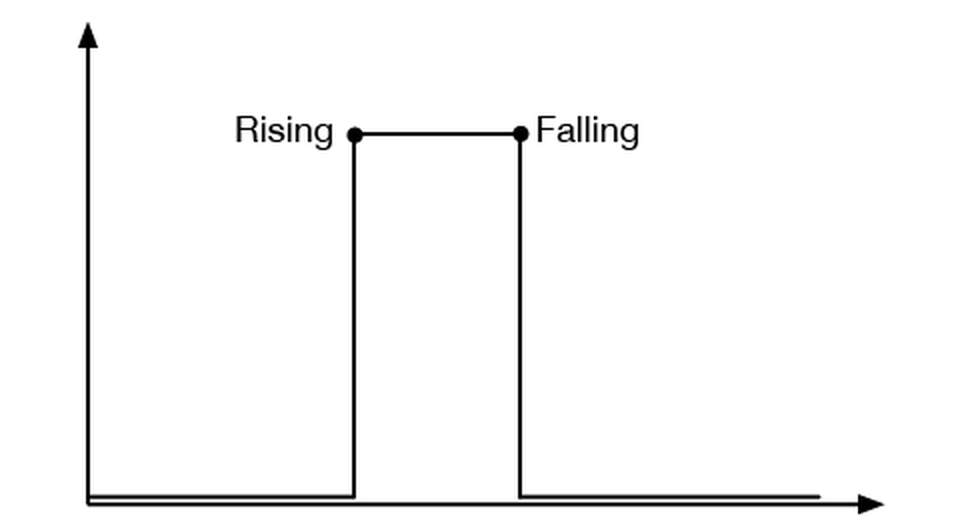
Since digital sensors can only sense two states, what’s important for detecting digital sensor change are the rising and falling edges.

Circuitry for detecting digital sensor change.
Digital sensor reading.
To detect the state change, we need to store the current state of a button as well as the previous state:
Analog sensor
It’s more complicated with analog sensor detection. We need to detect the peak value from the sensor. Like with the digital sensor, both the current and the previous states are tracked. To find the peak, we pick a threshold that would be below the peak. Each time the sensor value rises above the peak, the sensor value is stores as the peak. This happens continuously until the peak value is always above the sensor value.

Analog sensor change.

Circuitry for analog sensor change detection.
Reading analog sensor change. The LED light up every AFTER the sensor has peaked.
With analog sensors there are often noise in the sensor reading that interfere with peak readings. To remove the noise, the code is modified as such: