Lab 3: Analog Output

This week’s lab was about analog output. An example of an analog output is the change of brightness in a lamp. A digital output would merely turn the lamp on or off in this instance. A micro-controller such as an Arduino is digital and can only take digital inputs and produce digital outputs. Last week we learned that micro-controllers use an analog-to-digital converter (ADC) to take analog inputs.

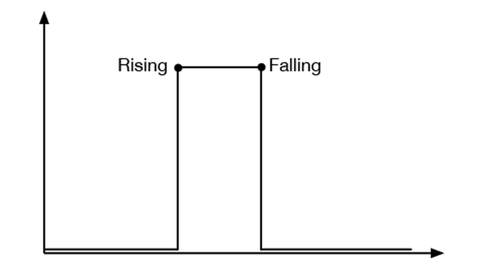
For analog output, the micro-controller creates pseudo-analog voltage with pulse width modulation (PWM). This means that the micro-controller basically fakes an analog voltage by producing a series of digital voltage pulses at regular intervals that are so fast (at micro or even nano seconds) it would be perceived as a varying voltage by the output device and humans.  What is really varying is the effective voltage produced by these pulses. The effective voltage changes depending on the ratio between the pulse width – the period of high pulse – and the period of low pulse.

Pulse width modulation.

Pulse width modulation.

For the lab, we changed the state of a servo motor and the tone produced by a Piezo capsule through analog output from the Arduino. The servo motor output was done through PWM, turning the motor 180 degrees each time. The tone change was through change in frequency. This is different from PWM in that the series of digital voltage pulses are not produced in regular intervals; instead the total width from low pulse to high pulse back to low changes, resulting in differing frequencies which in turn is perceived as changing tones to our ears.

Left: PWM. Right: Frequency.

Left: PWM. Right: Frequency.

Servo motor analog output.

Servo motor analog output.

Analog output: servo motor from Jiashan Wu on Vimeo.

Controlling the tone with photo sensors.

Controlling the tone with photo sensors.

Analog output: tones from Jiashan Wu on Vimeo.

Using the note constants to make a simple keyboard.

Using the note constants to make a simple keyboard.


Analog output: tones2 from Jiashan Wu on Vimeo.

Lab: Sensor change detection

Benedetta had recommended that we do this lab. Truthfully, I’m not sure why detecting the change in voltage output overtime is very useful.  Here are a few other questions I have:

  • How long should the detection time be?
  • How to detect the noise value of an analog sensor?

Digital sensor

Since digital sensors can only sense two states, what’s important for detecting digital sensor change are the rising and falling edges.

Screen Shot 2014-09-26 at 8.59.37 PM

Circuitry for detecting digital sensor change.

Circuitry for detecting digital sensor change.

Digital sensor reading.

Digital sensor reading.

To detect the state change, we need to store the current state of a button as well as the previous state:

Analog sensor

It’s more complicated with analog sensor detection. We need to detect the peak value from the sensor. Like with the digital sensor, both the current and the previous states are tracked. To find the peak, we pick a threshold that would be below the peak. Each time the sensor value rises above the peak, the sensor value is stores as the peak. This happens continuously until the peak value is always above the sensor value.

Analog sensor change.

Analog sensor change.

Circuitry for analog sensor change detection.

Circuitry for analog sensor change detection.

Reading analog sensor change. The LED light up every AFTER the sensor has peaked.

Reading analog sensor change. The LED light up every AFTER the sensor has peaked.

With analog sensors there are often noise in the sensor reading that interfere with peak readings. To remove the noise, the code is modified as such:

Lab 2: Input/output

For my second lab assignment, I connected a digital input and output circuit and an analog input circuit. (images below) The difference between a digital input and an analog input is that digital input can only sense two states (that’s why it’s also called binary input), on and off, and analog input can read a variable voltage. The range of an analog input is usually between 0 and the maximum voltage that the micro-controller can take. But the range can change depending on the physical context. In these instances, I should use the real range rather than the maximum range of the analog sensor.

There are various differences in working with digital input versus analog input. For one, an analog input requires an analog-to-digital converter (ADC) to read the voltage change and convert it into digital form, because the micro-controller can only read two input values, 0V and 5V. The ADC is built in the Arduino. With a digital input there is not need to convert the voltage.

Secondly, an analog input is less stable than a digital input. To smooth out the dips and spikes that goes into the circuit when inputing with an analog sensor, I need to decouple the input with a decoupling capacitor. (Capacitors are used to smooth out signals, by storing energy when the current is passing through and releasing it later.) Also, I should introduce a small delay after reading each sensor, to give the micro-controller time to stabilize before reading the next sensor.

Digital output is pretty straightforward – it turns something, such as a LED, on or off.

Issues: 

  • I had some issues with digital I/O when I tried to make my own switch with metal sheets. The LEDs lit and responded to the switch, but didn’t follow the correct order of the program, i.e. yellow off, red on when switch is off and the reverse then the switch is on.

Questions:

  • I’m still not sure how to find the real range of an analog sensor in practice.
  • I had encountered debouncing in another class when we used the Flora. What’s the difference between decoupling and debouncing?
  • How do you know which size of decoupling capacitor to use in an analog input circuit?

Other:

  • I briefly looked at the serial monitor for input data, but I still don’t totally understand how it works. I’ll look more into that.
Digital I/O

Digital I/O

Digital I/O with one button.

Digital I/O with one button.

Digital I/O with DIY button. **Issue: both LEDs are lit when the switch is off, when the yellow LED should be off.

Digital I/O with DIY button. **Issue: both LEDs are lit when the switch is off, when the yellow LED should be off.

Digital I/O with DIY switch2. **Issue: again, both LEDs are lit when the switch is off.

Digital I/O with DIY switch2. **Issue: again, both LEDs are lit when the switch is off.

Analog input.

Analog input.

Analog input with a potentiometer.

Analog input with a potentiometer.

Analog input with a force sensing resistor.

Analog input with a force sensing resistor.