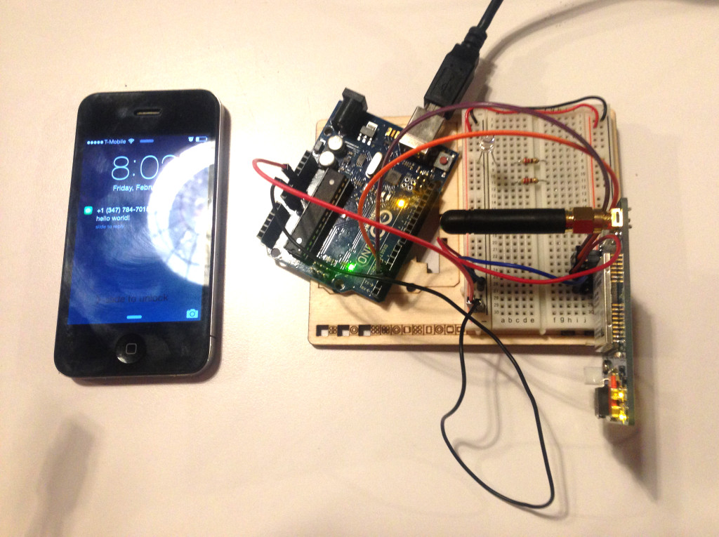
The first time I tried using the GSM module to send a text, I made the dumb mistake of not turning on the module. So it worked this time. I used the code that Benedetta had emailed us.
A modest next step: turn on a LED with a text. For now, I’m able to receive texts by sending them through the GSM module with CoolTerm, but I can’t receive any messages on the GSM module. I’ll need to figure out how to receive a message, match it, then change the LED pin output to HIGH.
UPDATE:
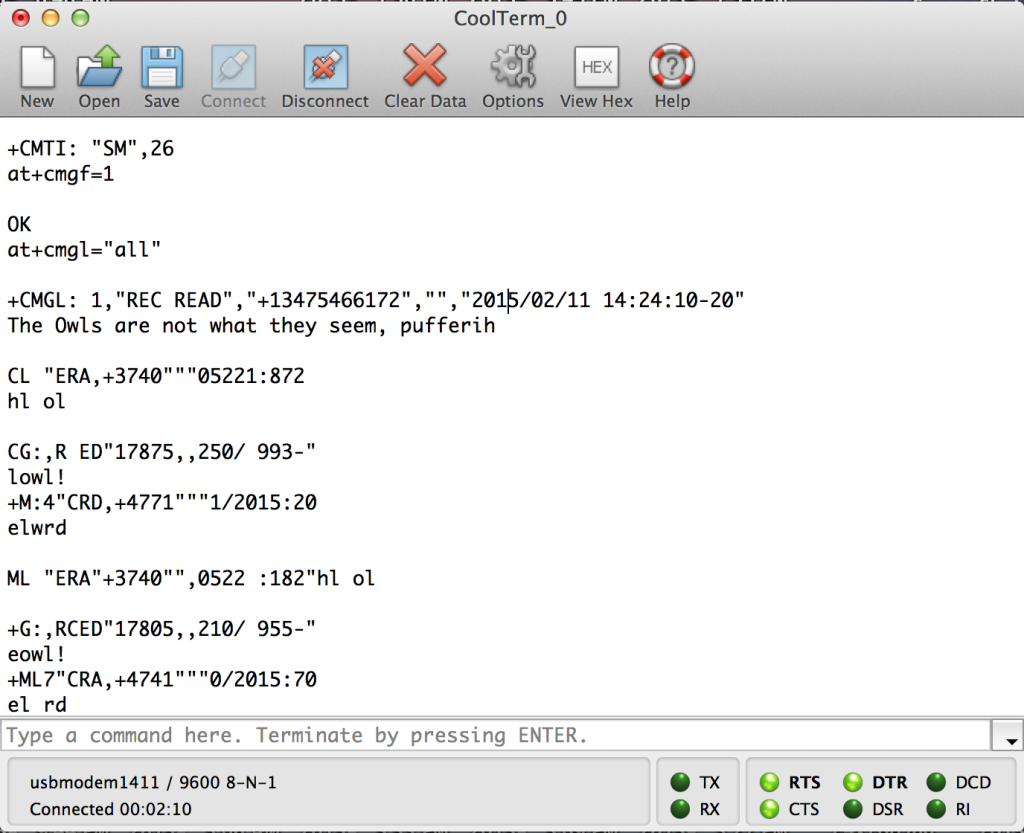
I attempted again with the white GSM module. I can read SMS with CoolTerm now, but there seems to be a long delay. It takes a few seconds for the messages to show. If I use the command AT+CMGL=”ALL”, only the first part of the first message would display correctly. The rest of the messages are in gibberish. I tried changing the delay that follows Serial.write(inChar); in the code. But this didn’t help.
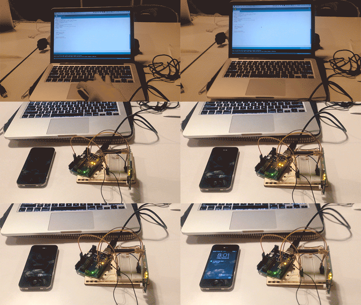
I also tried to turn the LED on by texting I, and turning it off by texting O. After about 10 secs of texting I, the LED would turn on. But typing O did not work. Also if I change the letter in the code from I to O, the LED would not turn on. Another issue I had was that after testing with my SIM card for a while, I wouldn’t be able to read anymore SMS on that card though I was still able to send SMS out. I had to switch to another SIM card to continue testing and reading SMS.
This is how it worked when I text “I” to turn on the LED:
Here’s the code:
Question
Is Serial.write(mySerial.(read)) writing +CMTI: “SM”,sms# each time? Perhaps this is why typing I would turn the LED on – because +CMTI contains the letter I. If this is the case, what is an effective way to check for +CMTI: “SM”,sms#, mySerial.print() the AT commands for reading SMS, skip through the metadata for the SMS, and read the actual SMS message?
